4L60E Repair
Guide - Assembly 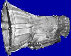
TRANSMISSION
INSPECTION and ASSEMBLY
Inspect
all gears, pinions, and carriers for signs of wear, galling, or other
damage. Replace parts as necessary. Closely inspect the
splines in
all locations, specifically the reaction sun shell hub and mating
reaction sun gear spline, the reaction carrier hub spline, input sun
gear, and the 1-2 planetary ring gear carrier hub. Any signs of
damage
or cracking in the carriers should indicate a need for
replacement.
Inspect the low-reverse clutch steels
and clutch discs. Any signs of heavy scuffing or burning should
indicate replacement. If the steels are intact, they can be
cleaned
and lightly honed, stoned flat, or ground to break any surface
glazing. Inspect the reverse clutch spring pack and springs for
damage, distortion, or breakage. Replace any parts as
necessary. Any clutch plates installed new or after solvent
cleaning must be soaked in clean transmission oil before assembly.
Assemble the low-reverse support
plate and clutch stack on a flat surface and check the overall
thickness of the stack at its extreme outer edge. If the
dimension is
below 1.200", the steels and/or clutch plates should be replaced. If
the dimension is between 1.200" and 1.240", it is acceptable.
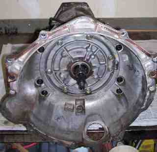
Install
the clutches into the case.
Test the reverse sprag clutch
operation. It should rotate with some amount of light resistance
in
the clockwise direction, and not rotate in the counterclockwise
direction at all.
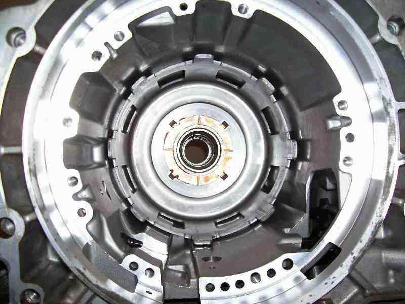
Assemble rear input planetary set,
sprag clutch, support plate, and large lock ring in reverse order of
disassembly.
Install the reaction sun gear and
transmission output shaft. Install the yellow lock ring onto the
shaft
to retain the reaction sun gear.
Install the appropriate thrust
washer
onto the low-reverse sprag hub and retain it with TransGel.
Lightly lubricate the reaction sun gear spline, then align and install
the reaction sun
shell. Install the thrust washer inside the shell and retain it
with a coating of TransGel.
Lightly lubricate and
install
the input planetary gear set assembly.
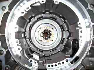
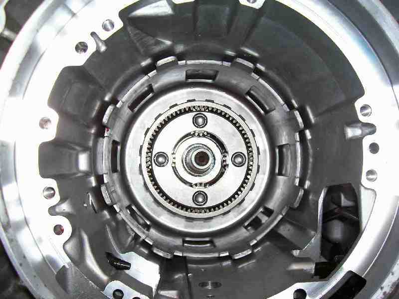
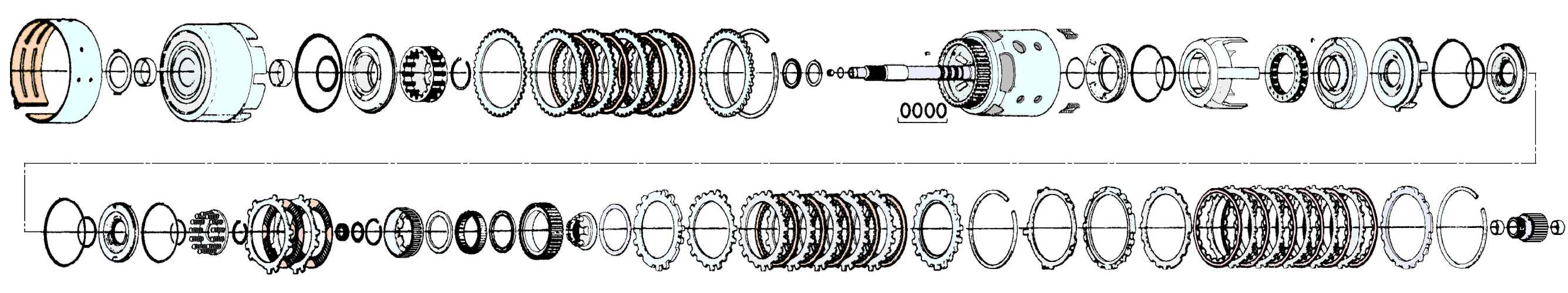
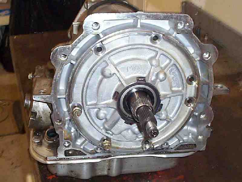
The entire reaction power path
assembly is depicted here for reference, but refer to the transmission
repair manual for specific instructions and details for each section.
(Click for larger
image)
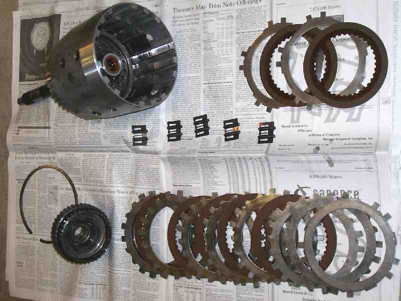
Disassemble the input drive shell
forward clutch, reverse clutch, sprag, direct clutch and inspect all
parts. 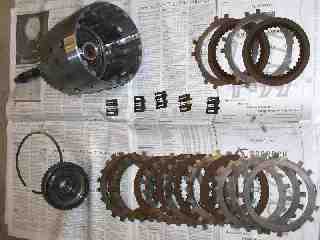
Remove
the lock ring from the 3-4 clutch backing plate, then the backing
plate. Remove the 3-4 clutch steels and plates, apply plate, and
retainer, being careful to maintain their order as removed. Inspect the
steels and clutch plates as described above, and replace any parts as
necessary.
Remove the lock ring for the forward
(direct) clutch, then the backing plate. Remove the forward
clutch
steels and plates, the Belleville or waved plate, and the apply plate,
and retainer, being careful to maintain their order as removed. Inspect
the steels and clutch plates as described above, and replace any parts
as necessary.
Remove the forward sprag clutch as an
assembly. Mark the orientation so you know which direction is
facing
forward on reassembly.
Remove the overrunning clutch plates
and steels. Inspect the steels and clutch plates as described
above,
and replace any parts as necessary.
Compress the overrunning clutch hub
against the spring and remove the shaft lock ring at the hub.
Relax
the compression and remove the overrunning clutch apply and forward
clutch apply pistons. Lift out the forward clutch housing and spring
package, and inspect the springs for damage, distortion, or
breakage.
Replace any parts as necessary.
Inspect the interior of the input
drum (torque drive drum) for indications of the clutch steels wearing
into the drum guides. Any grooves can cause clutch steels to
stick and
interfere with proper clutch engagement or release.
Replace seals and wipers as necessary
before assembly. With all parts intact, reassemble them in
reverse
order. The steels for the overrunning clutch should be
0.089-0.094'
thick after cleanup. Replace if necessary to maintain proper
clutch
stack thickness.
Inspect the forward sprag
clutch.
When viewed from the smaller hub side, the smaller splined hub should
be able to turn clockwise with minimal effort, and should not be able
to be turned counterclockwise with any amount of effort or force.
If
the sprag is intact, install it into the torque drum.
Assemble the forward (direct) clutch
in reverse order of disassembly. When installed with the support
plate
and lock ring, the total clearance of the stack should be between 0.030
and 0.063" as checked with a feeler gauge. Excessive clearance will
cause clutch slippage, and inadequate clearance can cause poor release
and burning of the clutch plates.
Assemble the 3-4 clutch and supports
in reverse order of disassembly. When installed with the support
plate
and lock ring, the total clearance of the stack should be between 0.060
and 0.085" as checked with a feeler gauge.
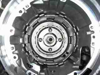
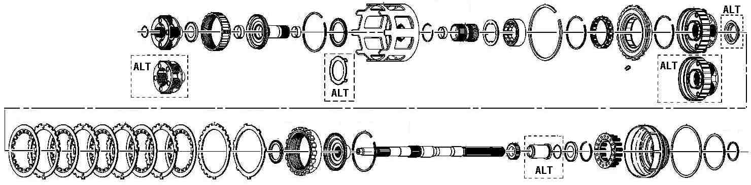
The entire input power path
assembly is depicted here for reference, but refer to the transmission
repair manual for specific instructions and details for each section.
(Click for larger
image)
Install the input drum assembly onto
the input planetary gear set and reaction sun shell. This can require
some patience and dexterity, as it will be necessary to align and
engage two sets of clutch plates with two different driven hubs.
Rotating the input drum to help align the clutches makes the task
possible, and up to seven plates on a stock clutch (you should have
counted them) need to be aligned to allow full engagement.
Remove the lock ring for the reverse
input clutch, then the backing plate, clutch plates and steels.
Remove
the Belleville (conical) plate, and inspect as previously directed for
wear or damage and replace any parts as necessary. Compress the reverse
input clutch spring and remove the retaining ring. Release the
compression and remove the spring assembly and piston. Inspect
and
replace seals as required. Reassemble the piston, spring and
retainer,
then the clutch stack in the order it was removed. Install the backing
plate and lock ring, and check the clutch clearance as previously
described. Allowable clearance is 0.040-0.076" for the
stack. Replace
clutches or steels as necessary to maintain this clearance.
Inspect and replace the shaft seals
on the input drum shaft. Inspect the input drum thrust bearing for
damage.
Install the band.
Install the reverse input drum by
aligning the clutch plates and rotating the drum as necessary to engage
all the plates on the inner hub, as well as the outer fingers into the
reaction sun shell.
Assemble
and install the 2-4 servo from the outside of the transmission housing,
making certain the clamp pin engages the band. Install the anchor
pin
for the stationary end of the band and retain it in place with masking
tape.
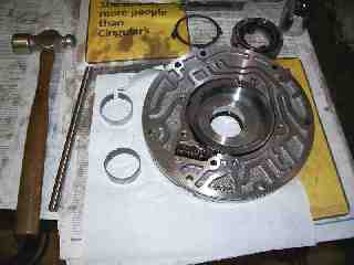
PUMP
Remove the pump body bolts and split
the pump halves. Remove the vanes and inspect for wear or
damage.
Lift out
the vane backing rings and pump rotor and inspect for scoring on either
face.
Inspect the pump cavity and end plates for wear of damage.
Inspect the
slew ring and springs closely (there are two concentric springs) for
damage or distortion.
Make sure the ring can pivot freely against the spring pressure.
Replace any damaged or worn parts as necessary.
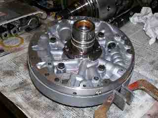
Drive
the front pump bushing out of the housing bore with a suitable
tool.
The pump bushing supports the entire mass of the torque converter and
can wear quickly. This is not an area to be overlooked.
Press or
drive a new pump bushing into the housing with a suitable tool.
Assemble
the pump with new vanes or reverse the existing vanes if they are
serviceable.
Lightly lubricate the pump rotor and vane support rings, and pack the
pump cavity with TransGel or Vaseline to
insure
fluid pickup once the transmission starts to operate.
Align
the pump
halves with a band clamp tool and tighten the body bolts to 18
ft/lb.
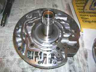
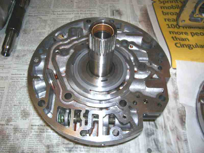
Lubricate the new pump bushing.
Install
the pressure regulator valve into the pump housing. Install the
thrust
washer on the rear face of the pump housing and retain it in place with
TransGel or Vaseline.

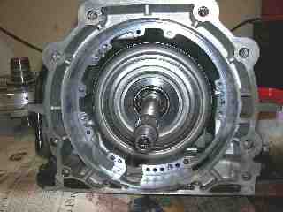
Install the pump into the front of
the transmission making sure the gasket is aligned properly, and the
pump bushings clear the input shaft without being damaged.
Tighten the
body bolts to 18 ft/lb.
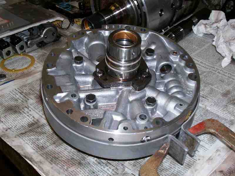
The pump housing will only orient one
way,
since there is only one area of the pump which has two bolts close
together. The orientation is self explanatory if you observe the
bolt
pattern.
There are M10 studs used professionally to help align
the
pump body for installation, but careful alignment will be
sufficient.
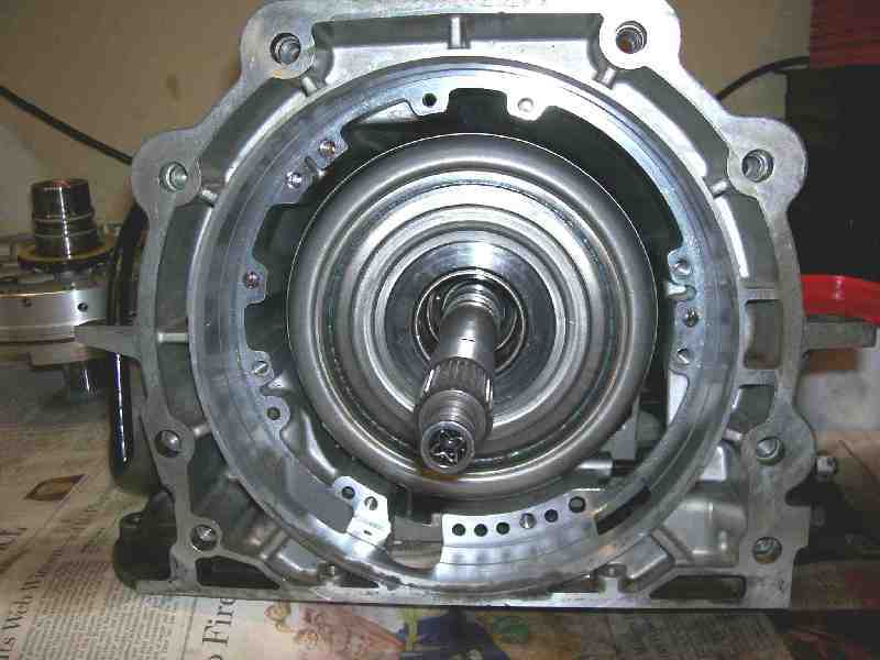
At
this point the transmission should be a nearly complete unit minus the
valve body. You should be able to turn the turbine (input) shaft
clockwise and the internal drag may drive the output shaft in the same
direction. Turning the input shaft counterclockwise will be more
difficult, and should result in an opposite rotation of the output
shaft. If the input (turbine) shaft does not react as described,
the
input sprag may be installed incorrectly or damaged. Check and
rectify
this before proceeding further.
There should be between 0.015-0.036"
total end play (axial) in the input shaft. Less than that can
mean the
pump is being bound or a clutch is not fully engaged, and more than
that can mean wear in a drum or thrust washer/bearing which will
require shimming. Shim washers are typically placed behind the thrust
bearing on the input drum before the reverse input clutch and drum are
installed.
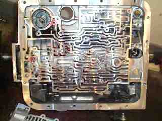
VALVE BODY
Valve body rebuilding will not be
covered in detail, since there are several variations. If you
suspect valve
body
damage, you can remove solenoids and valve spools to inspect them and
their bores. Repairs are typically done by reaming the bore
larger,
honing, or installing a wear sleeve after reaming, then honing to a
finished bore size. Scuffed or damaged spools must be
replaced.
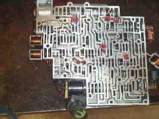
Aside from rebuilding the valve body,
the solenoids should be tested, along with the temperature sensor
and
pressure sensors. A plain ohmmeter will be sufficient. Your
transmission service manual should list the appropriate resistances for
the solenoid coils, and normal states of the pressure switches.
The
separator
plate should also be inspected closely where the check balls
seal.
Repeated operation of the checks will cause the balls to actually pein
the openings in the stamped steel plate until the holes are distorted
and enlarged.
Given enough wear, the balls can go through the plate and render the
check system ineffective. That can completely lock the
transmission
depending upon which valves are involved. Any wear should be
addressed. The plate can either be replaced or repaired.
Hard inserts
are available to replace the worn areas. Larger check balls can
also
be used, but 0.285" is about the safe diameter limit so that the balls
do not interfere with flow in the forward direction.
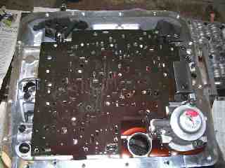
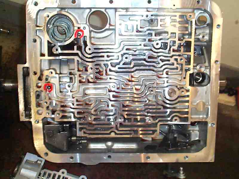
Install the single loose upper check
ball and accumulator spring, and check that the caged check ball is
still in the proper location.
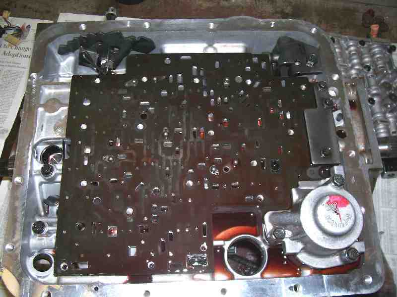
Install the upper separator plate
gasket and plate. Set the lower gasket onto the separator
plate.
Clean the valve body and insert the
lower body check balls in their appropriate locations.
NOTE: Two
balls share one channel near the center of the valve body.
Retain
the
balls in their respective holes or channels with TransGel or
Vaseline.
Install
the stamped steel plate on the left rear corner of the separator plate
and the accumulator body on the right rear corner of the plate.
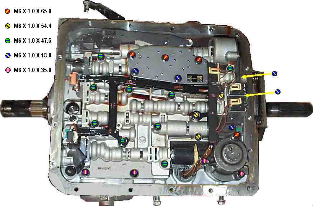
Insert
a few other valve body bolts in various locations to align the gasket
and plate properly, then tighten the three M6 X 18 hex head cap screws
for the stamped steel
plate to 100 in/lb, or about 8 ft/lb.
Tighten the two M6 X 35 and one M6 X 65 hex cap screws for the
accumulator to
the same torque specification.
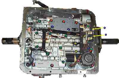 Pass the transmission main electrical
connector through the hole in the case and fold the wiring harness out
of the way. Insert the
linkage rod to
the
manual valve spool, then position the lower valve body and install all fasteners
in their appropriate positions.
Pass the transmission main electrical
connector through the hole in the case and fold the wiring harness out
of the way. Insert the
linkage rod to
the
manual valve spool, then position the lower valve body and install all fasteners
in their appropriate positions.
NOTE:
It is critical to install the bolts in their correct locations.
Installing a bolt which is too long can cause the bolt to seat against
the reaction sun shell or reverse input clutch housing/shell and
effectively lock the transmission.
Torque
all bolts to 100 in/lb.
Connect the electrical connectors to
the appropriate solenoids and install the TCC solenoid and valve.
Torque those two bolts to 100 in/lb. Insert the TCC PWM Signal
solenoid
valve into the remaining valve body bore and clip it in position.
Snap
the wiring harness conduit to the valve body bolts. Install the shift linkage detent arm
spring and roller.
 FINAL
ASSEMBLY
FINAL
ASSEMBLY
Install a new filter and seal, clean the
pan and magnet, and install it the oil pan.
This would also be a good time to install a drain plug in the pan to
ease any future service and routine maintenance.
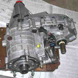
Set the transmission on the pan and
install the adapter bell housing.
NOTE:
The factory used a thread
adhesive
on these bolts, but given the typical galling and seizure these bolts
experience, I've used antiseize compound instead with no adverse
results.
Torque all the bell mounting fasteners to 45
ft/lb.
Seal
the main transmission electrical connector, oil cooler openings, vent
tube, and input shaft and output shaft areas,
then clean the transmission exterior.
If the
vehicle is AWD or 4WD, sealing and cleaning the transfer case would
also be advisable.
Inspect the transmission case seal
for the transfer case adapter or the tailshaft housing, and replace the
seal as necessary.
If appropriate, replace the rear bushing in the tailshaft housing and
install a new driveshaft yoke seal. Install the tailshaft housing and
seal the end with a suitable cap.
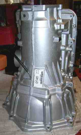
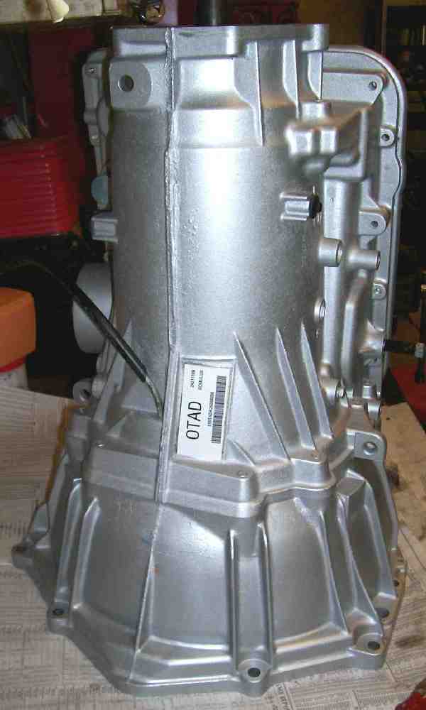
The transmission can now be
painted
and have a new alpha label installed.
In
preparation for installation into the vehicle, it would also be good to
clean the cross member, lines, and vehicle wiring harness.
Applying
antiseize compound to engine fasteners, chassis and mount bolts,
exhaust studs, and other various fasteners is always prudent.
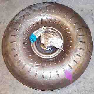 If it has not already been done,
drain the torque converter completely. Tip it, slosh it, agitate
it,
and do whatever is necessary to get all you can out of the converter
housing. A typical converter contains several quarts of fluid,
and any
contamination which resulted from the transmission failure is likely in
the oil within the converter. Draining it as much as practical
reduces
the contamination the new filter will experience and helps insure a
successful repair.
If it has not already been done,
drain the torque converter completely. Tip it, slosh it, agitate
it,
and do whatever is necessary to get all you can out of the converter
housing. A typical converter contains several quarts of fluid,
and any
contamination which resulted from the transmission failure is likely in
the oil within the converter. Draining it as much as practical
reduces
the contamination the new filter will experience and helps insure a
successful repair.
When the bulk of the oil is drained from
the
converter, placing it upside-down over a large steel container (a
coffee can works great for this) will allow nearly all the remaining
oil to drain out over several hours.
You should also inspect the hub of
the converter for visible wear. This is the part which mates the
pump
bushing, and they are common wear areas.
If the converter has
high
mileage, it may be better to replace it with a new or factory
remanufactured unit. Read the Home page and PARTS and UPGRADES section for the
full explanation.
Lubricate
the front pump seal and pump bushing with TransGel or transmission
fluid, then install the torque converter onto the transmission input
shaft. There are two splines to be engaged, and one drive lug (the
double slots on the main converter hub) to engage with the pump.
Carefully align the converter with the input shaft and slide it into
place. Rotate and lift/tilt the converter as necessary to engage
the
splines and pump drive lugs. When installed correctly, the converter
should slide all the way back to the point where it contacts the
adapter bell.


 Pass the transmission main electrical
connector through the hole in the case and fold the wiring harness out
of the way. Insert the
linkage rod to
the
manual valve spool, then position the lower valve body and install all fasteners
in their appropriate positions.
Pass the transmission main electrical
connector through the hole in the case and fold the wiring harness out
of the way. Insert the
linkage rod to
the
manual valve spool, then position the lower valve body and install all fasteners
in their appropriate positions. 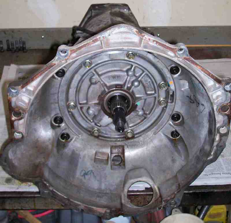 FINAL
ASSEMBLY
FINAL
ASSEMBLY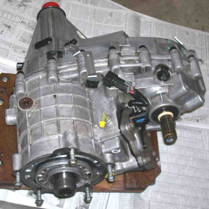
 If it has not already been done,
drain the torque converter completely. Tip it, slosh it, agitate
it,
and do whatever is necessary to get all you can out of the converter
housing. A typical converter contains several quarts of fluid,
and any
contamination which resulted from the transmission failure is likely in
the oil within the converter. Draining it as much as practical
reduces
the contamination the new filter will experience and helps insure a
successful repair.
If it has not already been done,
drain the torque converter completely. Tip it, slosh it, agitate
it,
and do whatever is necessary to get all you can out of the converter
housing. A typical converter contains several quarts of fluid,
and any
contamination which resulted from the transmission failure is likely in
the oil within the converter. Draining it as much as practical
reduces
the contamination the new filter will experience and helps insure a
successful repair.